Secondary storage
“Memory” usually refers to
storage
within the address space(s) of the processor. There is often some
secondary storage which is not directly addressable by the processor.
Instead, the storage will be intermediated by some I/O device.
There are various technologies which can be employed. Currently the
commonest are:
- Magnetic disk
- Optical disc
- ‘Flash’ memory
Any technology has its own advantages and disadvantages although all
of the above share some characteristics. In particular the storage
will be (effectively) permanent (even with the power off),
accesses will be in sizeable blocks rather than bytes or words,
accesses will be correspondingly slow and the price per bit
will probably be lower than that of the primary storage.
| Technology |
Permanent |
Access in... |
Random
access? |
Writeable? |
Moving
parts? |
| Magnetic disk |
Yes |
Blocks |
Sort of |
Yes |
Yes |
| Optical disc |
Yes |
Blocks |
Sort of |
Some |
Yes |
| SSD |
Yes |
Blocks |
Yes |
Yes - but
cycles limited |
No |
Magnetic disks
Most of this section focusses on magnetic disks –
specifically hard (non-interchangeable) drives. Technology has
kept their storage densities increasing (the first drive stored less
than 4 MB - 1956) so the price/bit is still lower than
semiconductor storage.
Hard disks are quite reliable, ‘permanent’ storage
devices which can be written as fast as they read. They are rather
slower than solid-state devices, especially having a long, and
unpredictable, latency.

Historically, interchangeable ‘floppy’ disks, which worked
on the same principles, were common. Their role in storing and
transporting data files has since been replaced by networks and USB
‘thumb drives’
They still survive, in a sense, as a common ‘save file’
icon.
Optical discs
Optical discs (yes, with a ‘c’ not a ‘k’) such as
CDs,
DVDs and
Blu-ray
share most of the properties of magnetic disk drives when in use. The
chief differences for the user are that the options for writing are
more limited and that medium is interchangeable (and cheaply
mass-producible).
SSD
A Solid
State Drive - sometimes (inaccurately!) “Solid State Disk” - uses
semiconductor
(‘Flash’)
storage which makes it more compact and more robust. There are no
moving parts; a consequence is that the read latency is reduced and is
constant since there is no waiting for the desired sector to arrive.
There is also no need to power motors. This makes the technology
appropriate for portable equipment
The nature of the technology is that the memory can be read rapidly
but is much slower to write to. Also, each write operation stresses
the device and does a small amount of damage: a device may be
guaranteed only up to (say) 100,000 write operations.
SSDs come in many (familiar) forms, some of which, such
as SD cards
and thumb
drives are interchangeable.
Note that Flash memory technology is not restricted to secondary
storage. Many devices have a parallel bus interface and can be used
in the primary address space.
Discussion exercise
Investigate and tabulate some typical read and write latencies and
bandwidths for contemporary secondary storage devices.
Discussion questions
-
Why would virtual memory paging be inappropriate on a device like a
tablet
computer?

-
How might Flash (or similar) memory be employed in a mobile 'phone?
(There may be more than one use.)
Disk drive details: magnetic, mostly
Nice (apparently silent) tour of
hard disk
structure and operation (14 mins. but may want to pause in
places).
There are some characteristics which are traditionally included when
describing disk access. Data is recorded (serially) on concentric,
circular tracks The disk rotates (doh!) carrying the data around: the
read head can only be at a single point over any track. There is thus
a delay whilst the desired data ‘comes around’. On
average, if started at a random time, this will take the time
for half a revolution, since sometimes the disk is in exactly
the right place, sometimes it has just missed the data and
(usually) it's somewhere in between.
Before that the head has to reach the correct track, which is called
“seeking”. This involves accelerating moving parts and
takes up some more time.
Once started the data is read at a speed governed by the bit
density and the rotation speed. The data is arranged in
blocks called ‘sectors’ and a sector is the minimum unit
of access. On the disk there will be a sector number so it can be
identified and a checksum of some sort to verify that the reading is
correct.
As far as possible, a single file will be organised so that its
sectors are consecutive on a track to reduce the waiting time once the
file reading has begun. If the head has to change tracks there may be
an offset – sometimes called a ‘skew’ – so
that the step time is accommodated.
Over time, as files of different sizes are written, modified and
deleted there may be ‘fragmentation’ where a single
file is scattered about a disk. Naturally this reduces performance.
O.S. software may, periodically be used to defragment the files
to restore best performance.
When performance may be particularly desirable, such as for the binary
utilities in common use
(e.g. /bin/...), and
contents are rarely modified the files may also be placed on tracks
near where the head ‘parks’, to reduce seek time.
Instructions
- Read different files and observe the time taken.
The latency for any file will vary according to the position of
the disk and the heads when the command is issued.
- The speed of the animation can be controlled to make particular
behaviours easier to see.
File properties
- Most of the files are the same length (10 sectors).
- The Red file is somewhat scattered across tracks but placed so
that the heads will meet the next sector when changing tracks.
- The Green file is distributed in a similar way to the Red file
but will miss the next sector when changing tracks, thus
necessitating a wait of nearly a whole rotation.
- The Blue file is half the length of the others, but badly
scattered across the disk.
- The Yellow file is stored neatly in consecutive sectors.
This simulation has the disk heads mounted on a sliding arm.
Floppy disk drives were typically built this way. Hard disk drives
usually use a rigid, pivoting arm which makes the drive more
compact.
However it also makes drawing it rather harder! It does not change
the principle of the drive's operation.
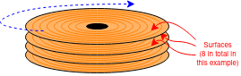
Real hard disks use both sides (surfaces) of the disk, usually with
many coaxial disks. There is a head for each surface, all sharing the
same moving arm. The set of tracks on each surface at the same radius
form a ‘cylinder’; changing surface to surface before
changing tracks may be preferred because switching heads is faster
than seeking – no parts need move.
There's a pull-apart video (6 mins.)
here  .
.
Some numbers
Do not memorise specific numbers: they will soon be out of date! Just
appreciate the orders of magnitude.
Areal
density – i.e. the number of bits which can be stored on a
disk – has also, roughly followed Moore's law. This means that
the disks have got physically smaller whilst the capacity has
increased enormously.
Values
vary but here are some representative figures:
- Rotation speed ~6000 rpm (100 Hz) - so ave. ~5 ms latency
- Seek time (heads to desired track) ~10 ms latency
- Data rate ~1 Gb/s: so ~100 MB/s or 1 MB in ~10 ms latency
- Total capacity: ~1 TB (+) per ‘box’ (i.e. 1000 GB)
Note that, for most transfers the mechanical delays, particularly the seek time, dominate the latency.
There are plenty of figures on the web, if you can decipher them.
All are still improving reasonably rapidly.
Interface
At time of writing a given ‘disk drive’ has considerable
‘intelligence’ and operates as a semi-autonomous unit with embedded processor(s) and some buffer RAM. Some may even contain their own cache.
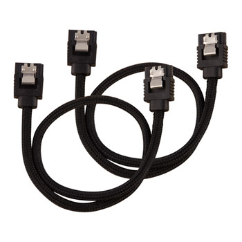
Image linked to Scan Computers of Horwich.
Other suppliers are available.
For a long time the most common interface between the computer and the
drive was the parallel
SCSI standard.
For convenience the current interfaces tend to use
the SATA
standard serial bus interface with smaller connectors and more
flexible wiring. SATA began with a bit-rate of 1.5 Gb/s which
doubled for SATA 2 and doubled again in SATA 3
(i.e. 6 Gb/s). divide numbers by 10 to get
the byte rate.
Note that a SATA link (even SATA 1) should be able to provide
enough bandwidth to avoid limiting the bandwidth the disk can
provide.
Divide by 10? Yes. Not just a convenient approximation for
mental arithmetic: the serial encoding is
“8b/10b”
which you can click on and read about but only if you're interested in
the engineering details.
RAID
RAID –
The Redundant Array of Inexpensive Disks
(sometimes “... Independent Disks”)
– is a bit confusing because the term is applied to solutions to
different problems. Here we will assert that the issues addressed
are:
These issues are addressed by using several, mechanically independent
disk drives which are virtualised to look like a single device.
RAID 0 provides higher bandwidth than a single drive by
distributing a file across an array of disks. This interleaves
the read operations as the drives can operate mechanically in
parallel. (It's like widening the bus again.)
In this context, the technique is typically referred to as
“striping”.
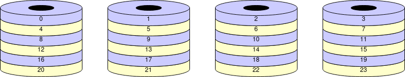
Question: why will RAID 0 reduce the reliability of the system?
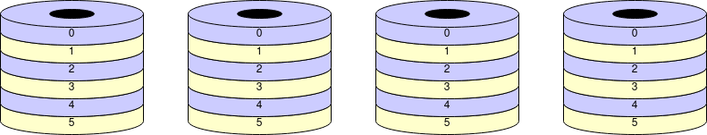
RAID 1 increases reliability by using
“mirroring” – keeping multiple copies of the
same data on different disks. Data are written in parallel to all the
disks and read from any copy. If one disk fails the system will still
work. This means cheaper (less reliable) individual disk units can
still provide a service despite a fault occurring.
Elaboration: This illustrates a general principle in
reliability engineering. To gain high reliability there are two,
non-exclusive approaches:
-
Fault avoidance.
Using (expensive) high-quality components which are unlikely to fail.
This suffers from ‘diminishing returns’ and can never
provide a system reliability as even as good as its
‘weakest’ component.
-
Fault
tolerance.
Using redundant parts so that single (and possibly more) faults do not
compromise the whole system.
This can provide higher reliability than the components it is
made from. The disadvantage is the cost, which may be financial, in
size, weight, power consumption ...
There are many variations and combinations: for example RAID 10
is a combination of the two schemes outlined above.
Next: Oliver and processors